How to Read Ohms on a Multimeter for Electrical
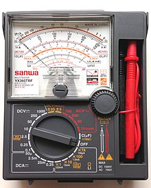
An analog multimeter, the Sanwa YX360TRF
A multimeter is a measuring musical instrument that can measure multiple electrical properties. A typical multimeter can measure voltage, resistance, and electric current, in which example it is too known equally a volt-ohm-milliammeter (VOM), as the unit of measurement is equipped with voltmeter, ammeter, and ohmmeter functionality. Some feature the measurement of boosted properties such as temperature and volume.
Analog multimeters employ a microammeter with a moving pointer to display readings. Digital multimeters (DMM, DVOM) accept numeric displays and have fabricated analog multimeters virtually obsolete every bit they are cheaper, more precise, and more physically robust than analog multimeters.
Multimeters vary in size, features, and price. They tin be portable handheld devices or highly-precise bench instruments. Cheap multimeters tin cost under US$ten, while laboratory-grade models with certified scale tin can cost over The states$5,000.
History [edit]

The first moving-arrow current-detecting device was the galvanometer in 1820. These were used to measure resistance and voltage by using a Wheatstone bridge, and comparing the unknown quantity to a reference voltage or resistance. While useful in the lab, the devices were very tedious and impractical in the field. These galvanometers were beefy and fragile.
The D'Arsonval–Weston meter motility uses a moving coil which carries a pointer and rotates on pivots or a taut band ligament. The coil rotates in a permanent magnetic field and is restrained by fine spiral springs which also serve to conduct electric current into the moving ringlet. It gives proportional measurement rather than simply detection, and deflection is independent of the orientation of the meter. Instead of balancing a span, values could be directly read off the musical instrument'south scale, which made measurement quick and easy.
The basic moving scroll meter is suitable only for direct current measurements, usually in the range of ten μA to 100 mA. It is hands adapted to read heavier currents by using shunts (resistances in parallel with the bones motion) or to read voltage using series resistances known as multipliers. To read alternating currents or voltages, a rectifier is needed. One of the earliest suitable rectifiers was the copper oxide rectifier developed and manufactured past Spousal relationship Switch & Bespeak Company, Swissvale, Pennsylvania, later part of Westinghouse Brake and Bespeak Company, from 1927.[i]
The first attested usage of the word "multimeter" listed by the Oxford English Dictionary is from 1907.[ii]
The invention of the first multimeter is attributed to British Post Function engineer, Donald Macadie, who became dissatisfied with the need to carry many separate instruments required for maintenance of telecommunications circuits.[3] Macadie invented an instrument which could measure out amperes (amps), volts and ohms, so the multifunctional meter was then named Avometer.[four] The meter comprised a moving coil meter, voltage and precision resistors, and switches and sockets to select the range.
The Automatic Coil Winder and Electrical Equipment Company (ACWEECO), founded in 1923, was set up to industry the Avometer and a coil winding machine besides designed and patented by MacAdie. Although a shareholder of ACWEECO, Mr MacAdie continued to work for the Post Office until his retirement in 1933. His son, Hugh S. MacAdie, joined ACWEECO in 1927 and became Technical Director.[5] [6] [4] The start AVO was put on sale in 1923, and many of its features remained almost unaltered through to the last Model 8.
General properties of multimeters [edit]
Whatsoever meter will load the circuit under test to some extent. For example, a multimeter using a moving whorl movement with full-calibration deflection current of 50 microamps (μA), the highest sensitivity ordinarily available, must draw at least l μA from the circuit under examination for the meter to reach the tiptop end of its scale. This may load a loftier-impedance circuit so much as to affect the circuit, thereby giving a depression reading. The full-scale deflection current may also exist expressed in terms of "ohms per volt" (Ω/V). The ohms per volt figure is often called the "sensitivity" of the instrument. Thus a meter with a fifty μA movement will have a "sensitivity" of 20,000 Ω/V. "Per volt" refers to the fact that the impedance the meter presents to the excursion under examination will be 20,000 Ω multiplied past the full-calibration voltage to which the meter is set up. For case, if the meter is set to a range of 300 V full scale, the meter's impedance will be 6 MΩ. 20,000 Ω/V is the best (highest) sensitivity bachelor for typical analog multimeters that lack internal amplifiers. For meters that do have internal amplifiers (VTVMs, FETVMs, etc.), the input impedance is stock-still by the amplifier circuit.
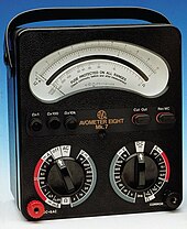
Avometer [edit]
The first Avometer had a sensitivity of threescore Ω/V, three direct current ranges (12 mA, ane.2 A, and 12 A), iii directly voltage ranges (12, 120, and 600 V or optionally 1,200 V), and a 10,000 Ω resistance range. An improved version of 1927 increased this to thirteen ranges and 166.6 Ω/V (six mA) movement. A "Universal" version having boosted alternating current and alternating voltage ranges was offered from 1933 and in 1936 the dual-sensitivity Avometer Model 7 offered 500 and 100 Ω/Five.[7] Between the mid 1930s until the 1950s, 1,000 Ω/V became a de facto standard of sensitivity for radio work and this effigy was frequently quoted on service sheets. Nonetheless, some manufacturers such every bit Simpson, Triplett and Weston, all in the USA, produced xx,000 Ω/V VOMs before the Second World War and some of these were exported. After 1945–46, 20,000 Ω/5 became the expected standard for electronics, but some makers offered even more sensitive instruments. For industrial and other "heavy-current" apply depression sensitivity multimeters continued to exist produced and these were considered more robust than the more sensitive types.
High-quality analog (analogue) multimeters go along to be made past several manufacturers, including Chauvin Arnoux (France), Gossen Metrawatt (Germany), and Simpson and Triplett (U.s.a.).
Pocket spotter meters [edit]
Pocket-watch-style meters were in widespread employ in the 1920s. The metal instance was typically connected to the negative connection, an arrangement that acquired numerous electric shocks. The technical specifications of these devices were often crude, for example the one illustrated has a resistance of just 33 Ω/V, a non-linear calibration and no zero aligning.
Vacuum tube voltmeters [edit]
Vacuum tube voltmeters or valve voltmeters (VTVM, VVM) were used for voltage measurements in electronic circuits where high input impedance was necessary. The VTVM had a fixed input impedance of typically one MΩ or more, commonly through employ of a cathode follower input circuit, and thus did not significantly load the circuit being tested. VTVMs were used before the introduction of electronic high-impedance analog transistor and field effect transistor voltmeters (FETVOMs). Modern digital meters (DVMs) and some modernistic analog meters also use electronic input circuitry to achieve high input impedance—their voltage ranges are functionally equivalent to VTVMs. The input impedance of some poorly designed DVMs (especially some early on designs) would vary over the course of a sample-and-hold internal measurement cycle, causing disturbances to some sensitive circuits under examination.
Boosted scales [edit]
Additional scales such as decibels, and measurement functions such as capacitance, transistor gain, frequency, duty cycle, display agree, and continuity which sounds a cablegram when the measured resistance is small have been included on many multimeters. While multimeters may be supplemented by more than specialized equipment in a technician's toolkit, some multimeters include boosted functions for specialized applications (temperature with a thermocouple probe, inductance, connectivity to a figurer, speaking measured value, etc.).
Functioning [edit]

A 4+ 1⁄2 -digit digital multimeter, the Fluke 87V
A multimeter is the combination of a DC voltmeter, AC voltmeter, ammeter, and ohmmeter. An un-amplified analog multimeter combines a meter motility, range resistors and switches; VTVMs are amplified analog meters and contain active circuitry.
For an analog meter movement, DC voltage is measured with a series resistor connected betwixt the meter movement and the circuit under exam. A switch (usually rotary) allows greater resistance to be inserted in serial with the meter movement to read higher voltages. The production of the bones full-scale deflection electric current of the movement, and the sum of the serial resistance and the motion's own resistance, gives the full-calibration voltage of the range. As an example, a meter motility that required one mA for total-scale deflection, with an internal resistance of 500 Ω, would, on a 10 V range of the multimeter, have 9,500 Ω of serial resistance.[viii]
For analog current ranges, matched depression-resistance shunts are connected in parallel with the meter motion to divert near of the electric current effectually the gyre. Again for the case of a hypothetical ane mA, 500 Ω motility on a 1 A range, the shunt resistance would exist just over 0.v Ω.
Moving ringlet instruments tin answer only to the average value of the current through them. To measure alternating current, which changes up and down repeatedly, a rectifier is inserted in the circuit so that each negative one-half bicycle is inverted; the consequence is a varying and nonzero DC voltage whose maximum value will be one-half the Air-conditioning top to peak voltage, assuming a symmetrical waveform. Since the rectified average value and the root mean foursquare (RMS) value of a waveform are but the same for a foursquare moving ridge, unproblematic rectifier-type circuits tin can but exist calibrated for sinusoidal waveforms. Other wave shapes crave a different scale factor to relate RMS and boilerplate value. This type of circuit normally has fairly limited frequency range. Since practical rectifiers have non-null voltage driblet, accuracy and sensitivity is poor at low AC voltage values.[ix]
To measure resistance, switches suit for a pocket-size battery inside the instrument to pass a current through the device nether test and the meter coil. Since the current available depends on the country of charge of the battery which changes over fourth dimension, a multimeter usually has an adjustment for the ohm scale to zero it. In the usual circuits constitute in analog multimeters, the meter deflection is inversely proportional to the resistance, so full-scale will be 0 Ω, and college resistance will correspond to smaller deflections. The ohms calibration is compressed, and then resolution is better at lower resistance values.
Amplified instruments simplify the pattern of the series and shunt resistor networks. The internal resistance of the coil is decoupled from the choice of the series and shunt range resistors; the series network thus becomes a voltage divider. Where AC measurements are required, the rectifier can exist placed subsequently the amplifier stage, improving precision at depression range.
Digital instruments, which necessarily contain amplifiers, use the same principles every bit analog instruments for resistance readings. For resistance measurements, usually a pocket-size abiding current is passed through the device under test and the digital multimeter reads the resultant voltage drop; this eliminates the scale compression found in analog meters, but requires a source of precise current. An autoranging digital multimeter can automatically arrange the scaling network and so the measurement circuits apply the full precision of the A/D converter.
In all types of multimeters, the quality of the switching elements is disquisitional to stable and accurate measurements. The best DMMs use gold plated contacts in their switches; less expensive meters utilise nickel plating or none at all, relying on printed circuit board solder traces for the contacts. Accuracy and stability (e.g., temperature variation, or aging, or voltage/current history) of a meter's internal resistors (and other components) is a limiting cistron in long-term accuracy and precision of the musical instrument.
Measured values [edit]

Contemporary multimeters tin can measure many values. The nigh common are:
- Voltage, alternating and direct, in volts.
- Current, alternating and direct, in amperes.
- The frequency range for which AC measurements are accurate is important, depends on the circuitry design and construction, and should be specified, and then users can evaluate the readings they accept. Some meters measure currents as low as milliamps or fifty-fifty microamps. All meters have a burden voltage (caused by the combination of the shunt used and the meter's excursion pattern), and some (fifty-fifty expensive ones) have sufficiently high brunt voltages that low electric current readings are seriously dumb. Meter specifications should include the burden voltage of the meter.
- Resistance in ohms.
Additionally, some multimeters as well mensurate:
- Capacitance in farads, but normally the limitations of the range are between a few hundred or thousand micro farads and a few pico farads. Very few general purpose multimeters tin can measure other important aspects of capacitor condition such equally ESR, dissipation gene, or leakage.
- Conductance in siemens, which is the inverse of the resistance measured.
- Decibels in circuitry, rarely in sound.
- Duty cycle as a percentage.
- Frequency in hertz.
- Inductance in henries. Like capacitance measurement, this is usually amend handled by a purpose designed inductance / capacitance meter.
- Temperature in degrees Celsius or Fahrenheit, with an appropriate temperature test probe, oftentimes a thermocouple.
Digital multimeters may also include circuits for:
- Continuity tester; a buzzer sounds when a excursion's resistance is depression enough (merely how depression is enough varies from meter to meter), and then the test must be treated equally inexact.
- Diodes (measuring forward drop of diode junctions).
- Transistors (measuring current gain and other parameters in some kinds of transistors)
- Battery checking for simple 1.five V and 9 V batteries. This is a electric current-loaded measurement, which simulates in-apply battery loads; normal voltage ranges draw very piffling electric current from the battery.
Various sensors tin be attached to (or included in) multimeters to have measurements such every bit:
- low-cal level
- sound pressure level
- acidity/alkalinity(pH)
- relative humidity
- very small current flow (downwardly to nanoamps with some adapters)
- very small resistances (down to micro ohms for some adapters)
- large currents – adapters are available which use inductance (AC current only) or Hall effect sensors (both Air-conditioning and DC current), usually through insulated clamp jaws to avoid direct contact with high current capacity circuits which tin can exist dangerous, to the meter and to the operator
- very loftier voltages – adapters are available which form a voltage divider with the meter'southward internal resistance, allowing measurement into the thousands of volts. Nevertheless, very high voltages often have surprising beliefs, aside from furnishings on the operator (maybe fatal); high voltages which really attain a meter's internal circuitry may internal harm parts, perhaps destroying the meter or permanently ruining its performance.
Resolution [edit]
Resolution and accuracy [edit]
The resolution of a multimeter is the smallest role of the scale which can be shown, which is scale dependent. On some digital multimeters it can exist configured, with higher resolution measurements taking longer to complete. For example, a multimeter that has a 1 mV resolution on a x V calibration tin can evidence changes in measurements in 1 mV increments.
Absolute accuracy is the error of the measurement compared to a perfect measurement. Relative accuracy is the error of the measurement compared to the device used to calibrate the multimeter. Most multimeter datasheets provide relative accuracy. To compute the accented accuracy from the relative accurateness of a multimeter add together the absolute accurateness of the device used to calibrate the multimeter to the relative accuracy of the multimeter.[ten]
Digital [edit]
The resolution of a multimeter is oftentimes specified in the number of decimal digits resolved and displayed. If the most significant digit cannot have all values from 0 to nine information technology is more often than not, and confusingly, termed a fractional digit. For instance, a multimeter which can read up to 19999 (plus an embedded decimal betoken) is said to read 4+ 1⁄two digits.
By convention, if the most significant digit tin can exist either 0 or 1, it is termed a half-digit; if information technology can accept higher values without reaching nine (oft 3 or 5), it may be called 3-quarters of a digit. A 5+ i⁄2 -digit multimeter would display one "half digit" that could only display 0 or 1, followed by five digits taking all values from 0 to 9.[11] Such a meter could show positive or negative values from 0 to 199999. A three+ 3⁄4 -digit meter tin can display a quantity from 0 to 3999 or 5999, depending on the manufacturer.
While a digital display can hands exist extended in resolution, the extra digits are of no value if not accompanied by intendance in the design and calibration of the analog portions of the multimeter. Meaningful (i.e., loftier-accuracy) measurements require a good understanding of the instrument specifications, skilful command of the measurement atmospheric condition, and traceability of the calibration of the instrument. Still, fifty-fifty if its resolution exceeds the accurateness, a meter can exist useful for comparing measurements. For example, a meter reading 5+ ane⁄ii stable digits may indicate that one nominally 100 kΩ resistor is nearly 7 Ω greater than another, although the error of each measurement is 0.2% of reading plus 0.05% of full-scale value.
Specifying "display counts" is another style to specify the resolution. Display counts give the largest number, or the largest number plus ane (to include the display of all zeros) the multimeter'due south brandish can show, ignoring the decimal separator. For example, a 5+ 1⁄2 -digit multimeter tin besides be specified every bit a 199999 brandish count or 200000 brandish count multimeter. Often the display count is just called the 'count' in multimeter specifications.
The accuracy of a digital multimeter may be stated in a two-term form, such as "±one% of reading +2 counts", reflecting the dissimilar sources of error in the instrument.[12]
Analog [edit]
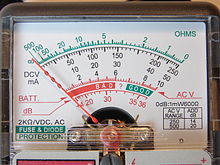
Display face of an analog multimeter
Analog meters are older designs, but despite being technically surpassed by digital meters with bargraphs, may even so be preferred[ co-ordinate to whom? ] by engineers[ which? ] and troubleshooters.[ original research? ] One reason given is that analog meters are more sensitive (or responsive) to changes in the circuit that is being measured.[ citation needed ] A digital multimeter samples the quantity being measured over time, and then displays information technology. Analog multimeters continuously read the test value. If there are slight changes in readings, the needle of an analog multimeter will try to rail it, as opposed to the digital meter having to expect until the next sample, giving delays betwixt each discontinuous reading (plus the digital meter may additionally require settling fourth dimension to converge on the value). The digital display value every bit opposed to an analog display is subjectively more difficult to read. This continuous tracking feature becomes important when testing capacitors or coils, for example. A properly operation capacitor should permit current to flow when voltage is applied, then the electric current slowly decreases to zero and this "signature" is easy to see on an analog multimeter but not on a digital multimeter. This is similar when testing a gyre, except the current starts low and increases.
Resistance measurements on an analog meter, in detail, tin be of depression precision due to the typical resistance measurement circuit which compresses the calibration heavily at the higher resistance values. Inexpensive analog meters may take merely a unmarried resistance scale, seriously restricting the range of precise measurements. Typically, an analog meter will have a panel adjustment to ready the aught-ohms scale of the meter, to recoup for the varying voltage of the meter battery, and the resistance of the meter's test leads.
Accurateness [edit]
Digital multimeters generally have measurements with accurateness superior to their analog counterparts. Standard analog multimeters mensurate with typically ±three% accurateness,[thirteen] though instruments of college accuracy are fabricated. Standard portable digital multimeters are specified to have an accuracy of typically ±0.v% on the DC voltage ranges. Mainstream bench-acme multimeters are available with specified accuracy of better than ±0.01%. Laboratory class instruments can have accuracies of a few parts per one thousand thousand.[14]
Accuracy figures need to be interpreted with care. The accuracy of an analog instrument usually refers to full-calibration deflection; a measurement of 30 Five on the 100 V calibration of a 3% meter is subject area to an fault of iii 5, 10% of the reading. Digital meters usually specify accuracy every bit a percentage of reading plus a percentage of full-scale value, sometimes expressed in counts rather than per centum terms.
Quoted accuracy is specified every bit being that of the lower millivolt (mV) DC range, and is known as the "bones DC volts accuracy" figure. College DC voltage ranges, current, resistance, AC and other ranges will unremarkably take a lower accuracy than the basic DC volts figure. Ac measurements simply meet specified accuracy within a specified range of frequencies.
Manufacturers can provide calibration services so that new meters may be purchased with a certificate of scale indicating the meter has been adjusted to standards traceable to, for case, the United states National Institute of Standards and Engineering science (NIST), or other national standards organization.
Examination equipment tends to drift out of calibration over time, and the specified accuracy cannot be relied upon indefinitely. For more expensive equipment, manufacturers and third parties provide scale services so that older equipment may be recalibrated and recertified. The cost of such services is disproportionate for inexpensive equipment; however extreme accuracy is not required for most routine testing. Multimeters used for critical measurements may exist part of a metrology plan to assure calibration.
A multimeter tin can exist assumed to be "average responding" to AC waveforms unless stated equally being a "true RMS" blazon. An boilerplate responding multimeter will only meet its specified accuracy on AC volts and amps for purely sinusoidal waveforms. A True RMS responding multimeter on the other mitt will come across its specified accuracy on AC volts and current with whatsoever waveform type up to a specified crest factor; RMS performance is sometimes claimed for meters which study authentic RMS readings only at certain frequencies (usually depression) and with certain waveforms (essentially always sine waves).
A meter'southward Ac voltage and current accuracy may have unlike specifications at different frequencies.
Sensitivity and input impedance [edit]
When used for measuring voltage, the input impedance of the multimeter must be very high compared to the impedance of the excursion existence measured; otherwise excursion operation may be affected and the reading will exist inaccurate.
Meters with electronic amplifiers (all digital multimeters and some analog meters) have a fixed input impedance that is high enough not to disturb most circuits. This is often either one or ten megohms; the standardization of the input resistance allows the use of external high-resistance probes which form a voltage divider with the input resistance to extend voltage range upwards to tens of thousands of volts. High-end multimeters generally provide an input impedance greater than 10 GΩ for ranges less than or equal to 10 V. Some loftier-end multimeters provide >10 Gigaohms of impedance to ranges greater than 10 5.[x]
Well-nigh analog multimeters of the moving-pointer type are unbuffered, and describe current from the circuit under test to deflect the meter pointer. The impedance of the meter varies depending on the basic sensitivity of the meter movement and the range which is selected. For example, a meter with a typical 20,000 Ω/Five sensitivity volition have an input resistance of 2 MΩ on the 100 V range (100 V × 20,000 Ω/5 = 2,000,000 Ω). On every range, at full-calibration voltage of the range, the full current required to deflect the meter motility is taken from the circuit under test. Lower sensitivity meter movements are acceptable for testing in circuits where source impedances are depression compared to the meter impedance, for example, power circuits; these meters are more than rugged mechanically. Some measurements in signal circuits require higher sensitivity movements so every bit not to load the circuit under exam with the meter impedance.[xv] [sixteen]
Sensitivity should not be confused with resolution of a meter, which is defined as the lowest signal change (voltage, current, resistance so on) that can change the observed reading.[sixteen]
For general-purpose digital multimeters, the lowest voltage range is typically several hundred millivolts AC or DC, but the lowest current range may be several hundred microamperes, although instruments with greater current sensitivity are bachelor. Multimeters designed for (mains) "electrical" use instead of general electronics engineering use will typically forego the microamps electric current ranges.
Measurement of low resistance requires pb resistance (measured by touching the test probes together) to be subtracted for all-time accurateness. This can be done with the "delta", "zero", or "naught" feature of many digital multimeters. Contact pressure to the device under test and cleanliness of the surfaces tin can impact measurements of very depression resistances. Some meters offer a four wire exam where two probes supply the source voltage and the others take measurement. Using a very high impedance allows for very low voltage drib in the probes and resistance of the source probes is ignored resulting in very authentic results.
The upper terminate of multimeter measurement ranges varies considerably; measurements over peradventure 600 volts, 10 amperes, or 100 megohms may require a specialized examination instrument.
Burden voltage [edit]
Every inline series-continued ammeter, including a multimeter in a current range, has a certain resistance. About multimeters inherently measure voltage, and pass a current to be measured through a shunt resistance, measuring the voltage developed across it. The voltage driblet is known as the burden voltage, specified in volts per ampere. The value can alter depending on the range the meter sets, since different ranges usually utilize unlike shunt resistors.[17]
The burden voltage can be significant in very low-voltage circuit areas. To check for its issue on accurateness and on external excursion operation the meter can exist switched to dissimilar ranges; the current reading should be the same and excursion operation should not be affected if burden voltage is not a trouble. If this voltage is meaning it tin can exist reduced (also reducing the inherent accuracy and precision of the measurement) by using a higher current range.
Alternating electric current sensing [edit]
Since the basic indicator system in either an analog or digital meter responds to DC only, a multimeter includes an Air-conditioning to DC conversion circuit for making alternating current measurements. Bones meters utilize a rectifier circuit to mensurate the average or peak accented value of the voltage, but are calibrated to evidence the calculated root hateful foursquare (RMS) value for a sinusoidal waveform; this will give right readings for alternating current every bit used in power distribution. User guides for some such meters requite correction factors for some simple non-sinusoidal waveforms, to allow the correct root hateful square (RMS) equivalent value to be calculated. More expensive multimeters include an Ac to DC converter that measures the true RMS value of the waveform within certain limits; the user manual for the meter may indicate the limits of the crest gene and frequency for which the meter scale is valid. RMS sensing is necessary for measurements on non-sinusoidal periodic waveforms, such as institute in sound signals and variable-frequency drives.
Digital multimeters (DMM or DVOM) [edit]

![]()
Modern multimeters are often digital due to their accuracy, immovability and extra features. In a digital multimeter the signal under test is converted to a voltage and an amplifier with electronically controlled proceeds preconditions the point. A digital multimeter displays the quantity measured as a number, which eliminates parallax errors.
Mod digital multimeters may accept an embedded computer, which provides a wealth of convenience features. Measurement enhancements available include:
- Machine-ranging, which selects the correct range for the quantity under test so that the virtually significant digits are shown. For instance, a four-digit multimeter would automatically select an advisable range to display 12.34 mV instead of 0.012 V, or overloading. Auto-ranging meters unremarkably include a facility to concur the meter to a particular range, because a measurement that causes frequent range changes can exist distracting to the user.
- Auto-polarity for direct-current readings, shows if the applied voltage is positive (agrees with meter lead labels) or negative (reverse polarity to meter leads).
- Sample and hold, which will latch the most contempo reading for test later the instrument is removed from the excursion under exam.
- Electric current-limited tests for voltage drop across semi usher junctions. While non a replacement for a proper transistor tester, and most certainly not for a swept curve tracer type, this facilitates testing diodes and a diversity of transistor types.[18]
- A graphic representation of the quantity under test, every bit a bar graph. This makes become/no-become testing easy, and also allows spotting of fast-moving trends.
- A low-bandwidth oscilloscope.[19]
- Automotive circuit testers, including tests for automotive timing and dwell signals (dwell and engine rpm testing is usually available every bit an pick and is not included in the basic automotive DMMs).
- Simple data acquisition features to record maximum and minimum readings over a given period, or to have a number of samples at fixed intervals.[xx]
- Integration with tweezers for surface-mount technology.[21] [ amend source needed ]
- A combined LCR meter for small-scale-size SMD and through-hole components.[22]
Modern meters may exist interfaced with a personal estimator by IrDA links, RS-232 connections, USB, or an musical instrument bus such as IEEE-488. The interface allows the computer to record measurements as they are made. Some DMMs tin can shop measurements and upload them to a computer.[23]
The first digital multimeter was manufactured in 1955 past Non Linear Systems.[24] [25] It is claimed that the first handheld digital multimeter was adult past Frank Bishop of Intron Electronics in 1977,[26] which at the fourth dimension presented a major breakthrough for servicing and fault finding in the field.
Analog multimeters [edit]

Inexpensive analog multimeter with a galvanometer needle display
A multimeter may be implemented with a galvanometer meter movement, or less often with a bargraph or faux pointer such as an liquid-crystal display (LCD) or vacuum fluorescent brandish.[ citation needed ] Analog multimeters were common; a quality analog instrument would cost about the aforementioned as a DMM. Analog multimeters had the precision and reading accuracy limitations described above, and and so were not congenital to provide the same accuracy as digital instruments.
Analog meters were intuitive where the trend of a measurement was more important than an exact value obtained at a particular moment. A change in angle or in a proportion was easier to interpret than a change in the value of a digital readout. For this reason, some digital multimeters additionally accept a bargraph as a second display, typically with a more rapid sampling rate than used for the primary readout. These fast sampling rate bargraphs have a superior response than the physical pointer of analog meters, obsoleting the older technology. With rapidly fluctuating DC, Ac or a combination of both, avant-garde digital meters were able to rails and brandish fluctuations ameliorate than analog meters whilst also having the ability to separate and simultaneously display DC and Air conditioning components.[27]
Analog meter movements are inherently more fragile physically and electrically than digital meters. Many analog multimeters feature a range switch position marked "off" to protect the meter movement during transportation which places a depression resistance beyond the meter movement, resulting in dynamic braking. Meter movements as separate components may exist protected in the same way by connecting a shorting or jumper wire between the terminals when not in employ. Meters which feature a shunt across the winding such as an ammeter may not require further resistance to arrest uncontrolled movements of the meter needle because of the low resistance of the shunt.
The meter motion in a moving pointer analog multimeter is practically ever a moving-gyre galvanometer of the d'Arsonval blazon, using either jeweled pivots or taut bands to back up the moving coil. In a basic analog multimeter the electric current to deflect the whorl and pointer is fatigued from the circuit being measured; it is usually an reward to minimize the current drawn from the circuit, which implies delicate mechanisms. The sensitivity of an analog multimeter is given in units of ohms per volt. For example, a very low-cost multimeter with a sensitivity of 1,000 Ω/5 would draw 1 mA from a excursion at full-scale deflection.[28] More expensive, (and mechanically more delicate) multimeters typically have sensitivities of 20,000 ohms per volt and sometimes higher, with 50,000 ohms per volt (drawing 20 microamperes at full calibration) being almost the upper limit for a portable, general purpose, non-amplified analog multimeter.
To avoid the loading of the measured circuit past the current drawn by the meter move, some analog multimeters employ an amplifier inserted betwixt the measured circuit and the meter move. While this increases the expense and complexity of the meter, by use of vacuum tubes or field consequence transistors the input resistance tin can be fabricated very high and contained of the current required to operate the meter move whorl. Such amplified multimeters are called VTVMs (vacuum tube voltmeters),[29] TVMs (transistor volt meters), FET-VOMs, and like names.
Considering of the absence of distension, ordinary analog multimeter are typically less susceptible to radio frequency interference, and so continue to have a prominent place in some fields even in a world of more accurate and flexible electronic multimeters.[30]
Probes [edit]

A multimeter can use many different test probes to connect to the circuit or device under examination. Crocodile clips, retractable hook clips, and pointed probes are the three most mutual types. Tweezer probes are used for closely spaced test points, as for example surface-mountain devices. The connectors are fastened to flexible, well insulated leads terminated with connectors appropriate for the meter. Probes are connected to portable meters typically by shrouded or recessed assistant jacks, while benchtop meters may use banana jacks or BNC connectors. ii mm plugs and binding posts have also been used at times, but are less commonly used today. Indeed, prophylactic ratings now crave shrouded assistant jacks.
The assistant jacks are typically placed with a standardized middle-to-center distance of iii⁄4 in (19 mm), to allow standard adapters or devices such as voltage multiplier or thermocouple probes to be plugged in.
Clamp meters clamp effectually a conductor carrying a current to measure without the need to connect the meter in series with the excursion, or make metallic contact at all. Those for Ac measurement use the transformer principle; clamp-on meters to mensurate pocket-sized current or direct electric current require more exotic sensors like for case hall effect based systems that measure out the nonchanging magnetic field to determine the current.
Prophylactic features [edit]

An example of input protection on the CAT-IV rated Fluke 28 Series 2 Multimeter
Well-nigh multimeters include a fuse, or two fuses, which volition sometimes foreclose damage to the multimeter from a current overload on the highest electric current range. (For added safety, test leads with fuses built in are available.) A common error when operating a multimeter is to set the meter to mensurate resistance or current, and and then connect it directly to a low-impedance voltage source. Unfused meters are often quickly destroyed by such errors; fused meters frequently survive. Fuses used in meters must carry the maximum measuring current of the instrument, but are intended to disconnect if operator fault exposes the meter to a depression-impedance fault. Meters with inadequate or unsafe fusing were not uncommon; this state of affairs has led to the creation of the IEC61010 categories to rate the safe and robustness of meters.
Digital meters are rated into 4 categories based on their intended application, equally set forth by IEC 61010-one[31] and echoed by country and regional standards groups such as the CEN EN61010 standard.[32]
- Category I: used where equipment is not directly continued to the mains
- Category Two: used on single phase mains terminal subcircuits
- Category III: used on permanently installed loads such as distribution panels, motors, and three-phase appliance outlets
- Category Four: used on locations where mistake current levels can be very high, such every bit supply service entrances, master panels, supply meters, and main over-voltage protection equipment
Each Category rating as well specifies maximum safe transient voltages for selected measuring ranges in the meter.[33] [34] Category-rated meters also characteristic protections from over-current faults.[35] On meters that allow interfacing with computers, optical isolation may exist used to protect attached equipment against high voltage in the measured circuit.
Expert quality multimeters designed to run into Category Ii and to a higher place standards include high rupture capacity (HRC) ceramic fuses typically rated at more than 20 kA capacity; these are much less likely to fail explosively than more common glass fuses. They will also include high energy overvoltage MOV (Metal Oxide Varistor) protection, and circuit over-current protection in the form of a Polyswitch.[ citation needed ]
Meters intended for testing in hazardous locations or for use on blasting circuits may require employ of a manufacturer-specified bombardment to maintain their safety rating.[ citation needed ]
DMM alternatives [edit]
A quality general-purpose electronics DMM is generally considered acceptable for measurements at signal levels greater than 1 mV or i μA, or below about 100 MΩ; these values are far from the theoretical limits of sensitivity, and are of considerable interest in some excursion design situations. Other instruments—substantially similar, simply with higher sensitivity—are used for accurate measurements of very modest or very large quantities. These include nanovoltmeters, electrometers (for very depression currents, and voltages with very loftier source resistance, such as 1 TΩ) and picoammeters. Accessories for more than typical multimeters permit some of these measurements, equally well. Such measurements are express past available applied science, and ultimately past inherent thermal noise.
Ability supply [edit]
Analog meters can measure voltage and current by using ability from the test circuit, simply require a supplementary internal voltage source for resistance testing, while electronic meters always require an internal power supply to run their internal circuitry. Manus-held meters utilise batteries, while bench meters usually use mains power; either arrangement allows the meter to test devices. Testing ofttimes requires that the component under test exist isolated from the circuit in which they are mounted, as otherwise devious or leakage current paths may distort measurements. In some cases, the voltage from the multimeter may turn active devices on, distorting a measurement, or in extreme cases even impairment an element in the circuit existence investigated.
See too [edit]
- Electronic exam equipment
- Electricity meter
References [edit]
- ^ "A New Electronic Rectifier", Fifty.O Grondahl & P.H. Geiger, Transactions, American Institution of Electrical Engineers, February 1927 pp. 358–366
- ^ "multimeter". Oxford English language Dictionary (Online ed.). Oxford University Press. Retrieved 14 March 2021. (Subscription or participating institution membership required.)
- ^ "Greater London Industrial Archaeology Society". glias.org.uk . Retrieved ii November 2010.
- ^ a b "AVO" (MediaWiki). gracesguide.co.uk . Retrieved 2 November 2010.
- ^ Imperial Higher Library Archives – Papers of Donald Macadie 1871–1956 MS2015/21
- ^ The Electrician 15 June 1923, p. 666
- ^ Advertizement – The Electrician, 1 June 1934
- ^ Frank Spitzer, Barry Howarth Principles of modern instrumentation, Holt, Rinehart and Winston, 1972 ISBN 0-03-080208-3 pp. 32–twoscore
- ^ Stephen A. Dyer, Wiley Survey of Instrumentation and Measurement, John Wiley & Sons, 2004 ISBN 0471221651, pp. 277–281
- ^ a b "Model 2002 Multimeter Specifications". Keithley Instruments.
- ^ "Digital Multimeter Measurement Fundamentals". National Instruments. Retrieved 26 Jan 2008.
- ^ Stephen A. Dyer, Wiley Survey of Instrumentation and Measurement, John Wiley & Sons, 2004 ISBN 0471221651, p. 290
- ^ Milton Kaufman. Handbook of electronics calculations for engineers and technicians. McGraw-Hill.
- ^ Keysight Technologies. "Keysight 3458A Digital Multimeter Data Sheet" (PDF). Keysight Technologies . Retrieved 31 July 2014.
- ^ Horn, Delton (1993). How to Test Almost Everything Electronic. McGraw-Colina/TAB Electronics. pp. iv–half-dozen. ISBN0-8306-4127-0.
- ^ a b Siskind, Charles South. (1956). Electrical circuits.
- ^ "Caption of brunt voltage by multimeter manufacturer Fluke". Fluke. Retrieved 2 November 2010.
- ^ Goldwasser, Samuel. "Basic Testing of Semiconductor Devices". Retrieved 28 January 2007.
- ^ Extech Instruments. "Extech v MHz Dual Channel Multiscope". Retrieved 28 January 2007.
- ^ "Extech Dual Channel, Datalogging multimeter". Extech Instruments. Archived from the original on 3 Apr 2007. Retrieved 28 January 2007.
- ^ Siborg Systems Inc. "Digital Multimeter Smart Tweezers from Siborg". Retrieved 23 April 2008.
- ^ Accelerate Devices Inc. "Smart Tweezers Digital Multimeter/LCR Meter" (PDF). Archived from the original (PDF) on 9 January 2007. Retrieved 20 Jan 2009.
- ^ Fluke Manufacturing. "Logging and analyzing events with FlukeView Forms Software" (PDF) . Retrieved 28 January 2007.
- ^ "Gauging the touch on of DVMs". EETimes.com. Retrieved 26 January 2008.
- ^ Dyer, Stephen (2001). Survey of Instrumentation and Measurement. p. 286. ISBN0-471-39484-X.
- ^ "Intron Electronics | About". world wide web.intronelectronics.com.au . Retrieved 17 July 2016.
- ^ Smith, Joe (24 August 2014). ""Brymen BM869s vs Fluke"". YouTube. Archived from the original on 17 November 2021. Retrieved 17 March 2020.
- ^ Frank Spitzer and Barry Horwath Principles of Modern Instrumentation, Holt, Rinehart and Winston Inc., New York 1972, no ISBN, Library of Congress 72-77731, p. 39
- ^ "The Incomplete Idiot's Guide to VTVMs". tone-cadger.com. Archived from the original on 6 October 2003. Retrieved 28 Jan 2007.
- ^ Wilson, Mark (2008). The ARRL Handbook for Radio Communications. ISBN978-0-87259-101-1.
- ^ "Safety Standard IEC 61010-1 since 1.1.2004". Archived from the original on ii December 2006.
- ^ Rubber requirements for electric equipment for measurement, control and laboratory use. Full general requirements. 1993. ISBN0-580-22433-3.
- ^ Dyer, Stephen (2001). Survey of Instrumentation and Measurement. p. 285. ISBN0-471-39484-X.
- ^ "Anatomy of a high-quality meter". Archived from the original on 18 Oct 2006. Retrieved 5 November 2015.
- ^ Mullin, Ray (2005). Electric Wiring: Residential. Thompson Delmar Learning. p. 6. ISBNane-4018-5020-0.
External links [edit]
- How to use a multimeter, sparkfun
- How to select a Multimeter – Discusses the key considerations to select the right multimeter.
- Multimeter Tutorial – Lots of useful information on Digital multimeter usage.
- Beginners' Guide to the 830B Multimeter – Discusses the many uses of a inexpensive digital multimeter in the home.
- How to Determine Digital Multimeter Accurateness
- ABCs of Multimeter safety – (PDF)
- Digital Multimeter – From theory to utilize
- Multimeters and How to Employ Them
- DC Metering Circuits chapter from Lessons In Electric Circuits Vol 1 DC free ebook and Lessons In Electric Circuits series.
Source: https://en.wikipedia.org/wiki/Multimeter
Enviar um comentário for "How to Read Ohms on a Multimeter for Electrical"